
Minor connector placement in RPD frameworks is governed by specific rules for each connector type. Here is what determines correct form, position, and junction design.
Table of contents [Show]
- Introduction
- Bulk and Rigidity: The Starting Point for Any Minor Connector
- Design Rules For Minor Connectors That Sit Between Teeth
- Design Rules For Minor Connectors That Contact Guiding Planes
- Design Rules For Minor Connectors That Retain The Denture Base
- Design Rules For Minor Connectors With Bar Clasp Approach Arms
- Conclusion
- References
Introduction
Knowing what a minor connector is and knowing how to design one correctly are two different things. Part 1 of this series covered definitions, functions, and the four connector types. This post goes one level deeper: where each type should sit, what shape it should take, and why the wrong placement creates problems that cannot be corrected after casting.
The principles here apply across connector types, but each type has its own specific requirements. Working through them in order is the most efficient way to build a complete picture.
Bulk and Rigidity: The Starting Point for Any Minor Connector
Minor connectors must be rigid. This is not optional. The entire force transfer mechanism depends on it. If a minor connector flexes under load, the functional stresses that should be distributed across the arch get absorbed locally instead, concentrating at the connection point and eventually leading to framework fatigue or inadequate support of the abutment teeth.
At the same time, bulk cannot be added without limit. A minor connector that is too thick in the wrong location will press on soft tissue, impinge on tongue space, or create areas where food accumulates. The design goal is sufficient bulk in the right cross-sectional direction, tapered appropriately where the connector meets teeth and soft tissue.
Design Rules For Minor Connectors That Sit Between Teeth
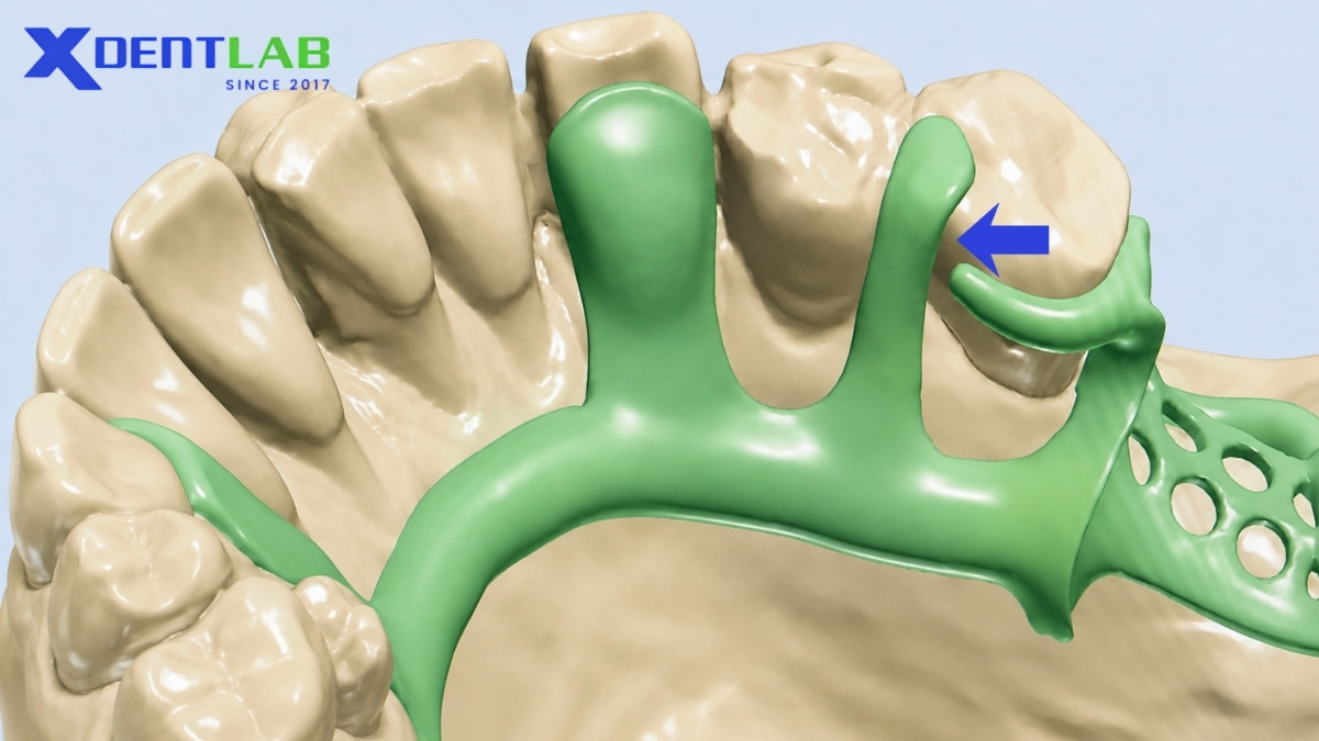
Embrasure minor connectors sit in the space between two adjacent teeth. They are the type most influenced by their immediate environment, and their design is governed by three rules that work together.
Place in the Embrasure, Not on a Convex Surface
A connector positioned on the curved outer surface of a tooth creates a pressure point and becomes immediately noticeable to the tongue. Placing it inside the embrasure keeps it out of direct tongue contact and distributes its presence across a concave space rather than a convex one.
The connector should run vertically from the major connector through the embrasure, crossing the gingival area as briefly as possible. Gingival tissue coverage should be minimized. The broader and longer the crossing, the greater the risk of irritation and inflammation over time.
Relieve the Gingival Crossing
Any metal that passes over the free gingival margin must be relieved. This means there is a deliberate gap between the connector and the soft tissue at that point. Without relief, the connector impinges on the tissue during function, causing chronic irritation that no amount of good oral hygiene will fully offset.
Block Out the Deepest Part of the Embrasure
The floor of the interdental embrasure is not available for connector contact. That area must be blocked out during framework design. If the connector reaches into that space, it will either interfere with seating and removal, or create a wedging force against the adjacent teeth. Neither outcome is acceptable.
Design Rules For Minor Connectors That Contact Guiding Planes
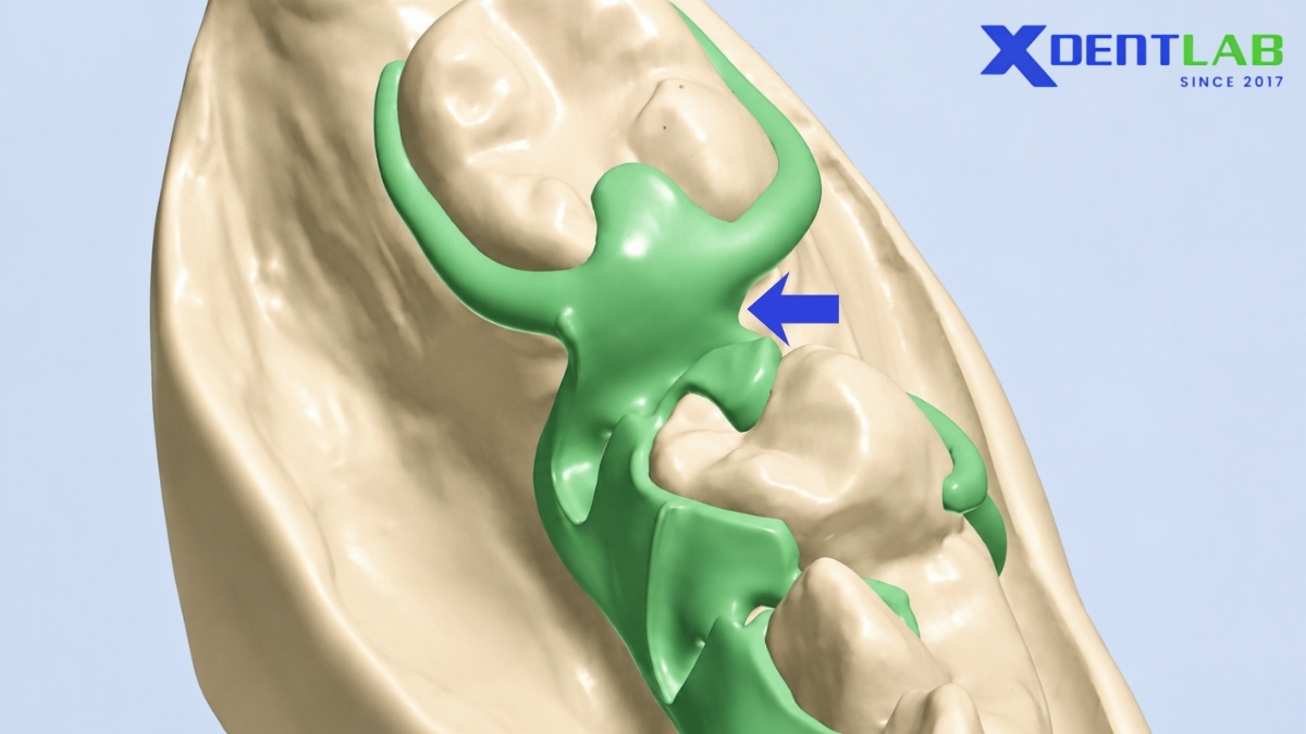
When a minor connector contacts the guiding plane surface of an abutment tooth adjacent to an edentulous space, its cross-sectional shape matters more than its position alone.
The connector must be broad in the buccolingual direction. A wide contact with the guiding plane generates effective frictional resistance that controls the path of insertion and removal. Narrow contact reduces that guidance effect significantly.
At the same time, the connector must be thin in the mesiodistal direction. The reason is straightforward: a prosthetic tooth needs to occupy the space next to the abutment in a natural position. A thick connector in that direction displaces the artificial tooth buccally or leaves a visible gap. Neither reflects acceptable aesthetics or function.
When an artificial tooth will be placed directly against this connector, the connector's greatest bulk should sit toward the lingual side of the abutment. This keeps the metal out of the zone where the prosthetic tooth contacts the abutment, allowing a more natural tooth-to-tooth relationship on the buccal side.
Design Rules For Minor Connectors That Retain The Denture Base
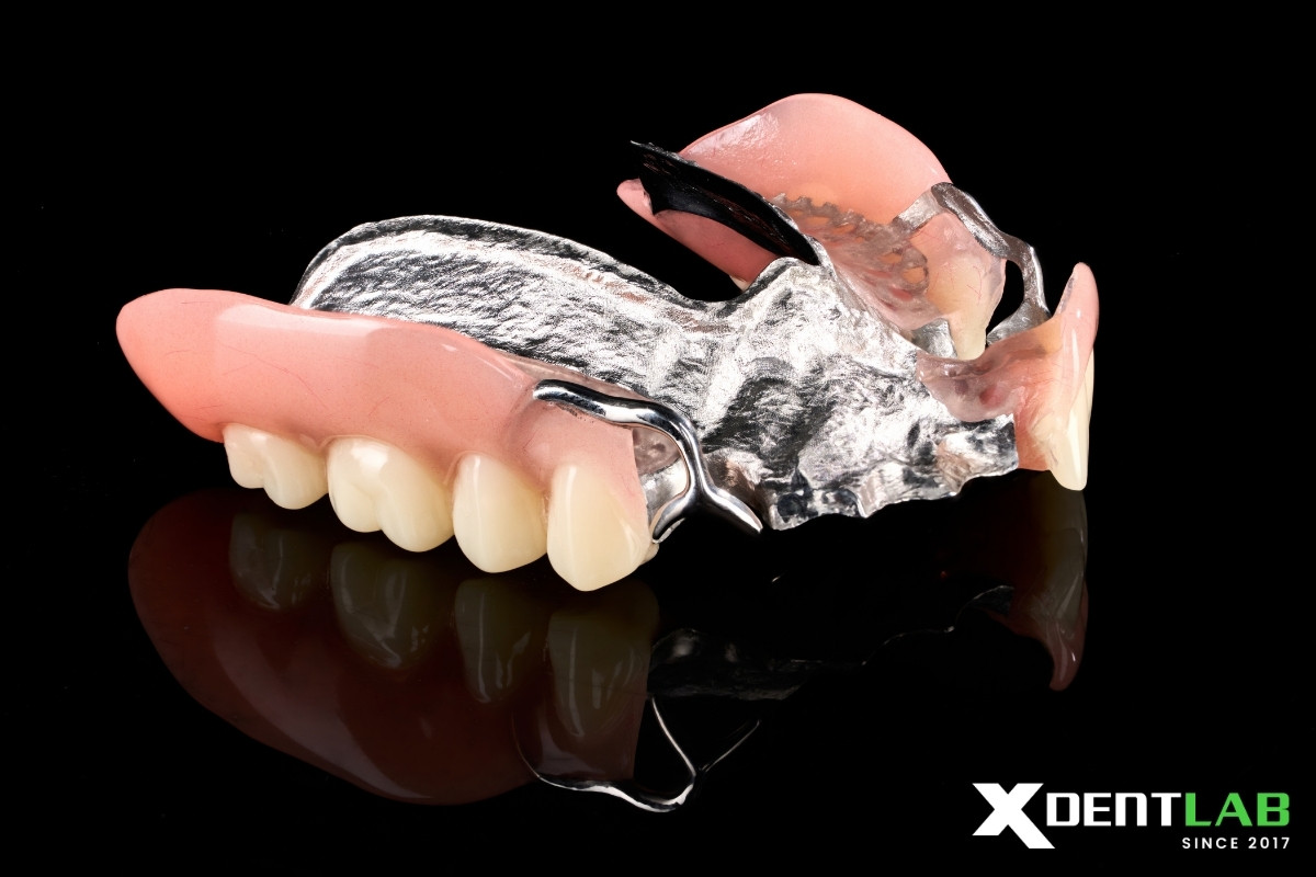
The minor connector that retains the acrylic resin denture base must be designed to sit completely within the denture base after processing. No part of it should be visible or palpable at the surface. This is not just an aesthetic requirement. If the connector is not fully embedded, the resin base will have a weak perimeter with no metal support at its edges.
Where this connector meets the major connector, the junction must be a butt joint formed at 90 degrees or less. Angles greater than 90 degrees reduce the mechanical strength of that connection and compromise the bond between the resin base and the metal framework.
Beyond the junction angle, the two arches have different extension requirements.
Mandibular Distal Extension Base
For the lower arch, the denture base retention connector should extend posteriorly to cover approximately two thirds of the edentulous ridge length. It should include elements on both the lingual and buccal aspects of the ridge.
This bilateral coverage serves two purposes. First, it increases the overall strength of the denture base. Second, it helps reduce the dimensional distortion that occurs when acrylic resin is processed. Resin shrinks as it cures. A connector that spans the ridge from both sides creates a more balanced constraint against that shrinkage, reducing the risk of a warped base after processing.
The connector must also be designed so it does not conflict with the arrangement of artificial teeth. Planning that clearance before the wax pattern is finalized avoids having to compromise either the connector geometry or the tooth position.
Maxillary Distal Extension Base
For the upper arch, the connector should extend the full length of the residual ridge, not just two thirds. A ladder-like or mesh-like design is appropriate for maxillary cases. The extended coverage reflects the longer, flatter ridge anatomy typical of the maxilla, where a shorter connector would leave the posterior resin base unsupported.
A bar-type clasp arm approaches the tooth from below, traveling from an apical direction rather than descending from an occlusal rest. The minor connector that forms this approach arm has specific requirements that do not apply to other connector types.
The taper must be smooth and even from the point where the arm originates at the major connector to the point where it terminates at the tooth. An uneven taper creates stress concentrations and makes the arm harder to adjust without distortion. A uniform taper from origin to terminus is the standard.
The second constraint is more critical: the approach arm cannot cross a soft tissue undercut. If the tissue contour between the major connector and the tooth surface curves inward at any point, the bar arm would need to deflect into or over that undercut to reach the tooth. That path is not available. The undercut must be blocked out in parallel during the design phase so the arm follows a straight, unobstructed path to the tooth.
Ignoring this requirement causes two problems. During insertion, the approach arm will impinge on the tissue in the undercut zone. During removal, it will either drag across that tissue or lever against the abutment. Both outcomes accelerate tissue damage and abutment stress over time.
Conclusion
Each placement rule for minor connectors exists for a specific reason, and most of those reasons are mechanical or biological rather than cosmetic. A connector that is correctly positioned but inadequately relieved at the gingival crossing will cause tissue problems. One that has the right relief but wrong junction angle will develop a weak base connection. One with proper extension but a taper that is uneven will fatigue earlier than expected.
The rules do not function in isolation. They compound. Getting most of them right while missing one often produces a framework that looks acceptable at delivery but fails gradually in service.
References
- Carr AB, Brown DT (2011) McCracken's Removable Partial Prosthodontics. 12th edn, Mosby, 45.
- https://codental.uobaghdad.edu.iq/wp-content/uploads/sites/14/2018/11/Lec-10-Minor-connectors.pdf
About XDENT LAB:
We are experts in Lab-to-Lab Full Service from Vietnam, with the signature services of Removable, meet U.S. market standards, FDA-registered, ISO 13485-certified. Founded in 2017, from local root to global reach, we scale with 2 Factories with over 100+ employees.
Our Commitments Built on “Trusted. Commitment. Quality”
- Commit to Large-Scale Manufacturing, high volume, remake rate < 1%.
- Commit to 5-Year Warranty
- Commit to Competitive Price
XDENT LAB | A Trusted Lab-to-Lab Service from Vietnam
Share this post:
Related Posts
Explore cast metal framework partial dentures, including design principles, material selection, lab workflow, fit, hygiene, and long-term clinical performance.
Not all occlusal rests are the same. Here is what distinguishes the extended, interproximal, internal types, and the clinical situations each one is designed for.
Explore lab-to-lab workflow and QC for implant-supported fixed prostheses, from fit and materials to retrievability, hygiene design, and consistency.

