
A clinical overview of the six maxillary major connector types in RPD design, and the design method used to select the right one.

Table of contents [Show]
Introduction
The major connector is the structural backbone of any removable partial denture (RPD). It joins the two sides of the framework into a single rigid unit, and every other component such as rests, clasps, indirect retainers, depends on it holding its shape under load. Get the connector wrong, and no amount of precision elsewhere in the design will compensate.
Maxillary major connectors are often treated as the simpler half of the equation compared to mandibular major connectors, since the palate offers more surface area and fewer anatomical obstacles than the lingual and labial spaces of the mandible. That assumption is only half true. The extra surface area gives the maxillary arch more room to work with, but it also means more legitimate ways to balance rigidity, coverage, and comfort within that space. Each maxillary connector type reflects a different point on that trade-off, and getting the choice wrong has a direct, measurable effect on rigidity, tissue health, and patient satisfaction.
This article covers what a maxillary major connector is required to do, the six recognized types, the criteria used to select between them, and Blatterfein's five-step design method, which remains the standard framework for working through a case systematically.
The Role of a Maxillary Major Connector
A maxillary major connector has five functional requirements:
- Rigidity: It must resist flexing under occlusal load. A connector that flexes transmits torque to the abutment teeth instead of distributing it across the arch.
- Unification: It joins the two sides of the framework into a single functional unit.
- Tissue tolerance: It must stay clear of the free gingival margins and any unyielding anatomical structures.
- Support for indirect retention: Where indirect retainers are required, the connector must provide a stable attachment point.
- Minimal bulk: It should occupy the least palatal space necessary to meet the first four requirements, since excess bulk interferes with tongue space and speech.
The palate accommodates these requirements more easily than the mandibular arch does. It offers a larger bearing surface, generally healthier tissue, and no equivalent to the floor-of-mouth or lingual frenum constraints that limit mandibular connector design. That extra room is exactly why the six recognized maxillary designs range so widely, from narrow bars to full palatal plates: more usable surface area means more legitimate ways to balance rigidity, coverage, and comfort.
Six Types of Maxillary Major Connectors
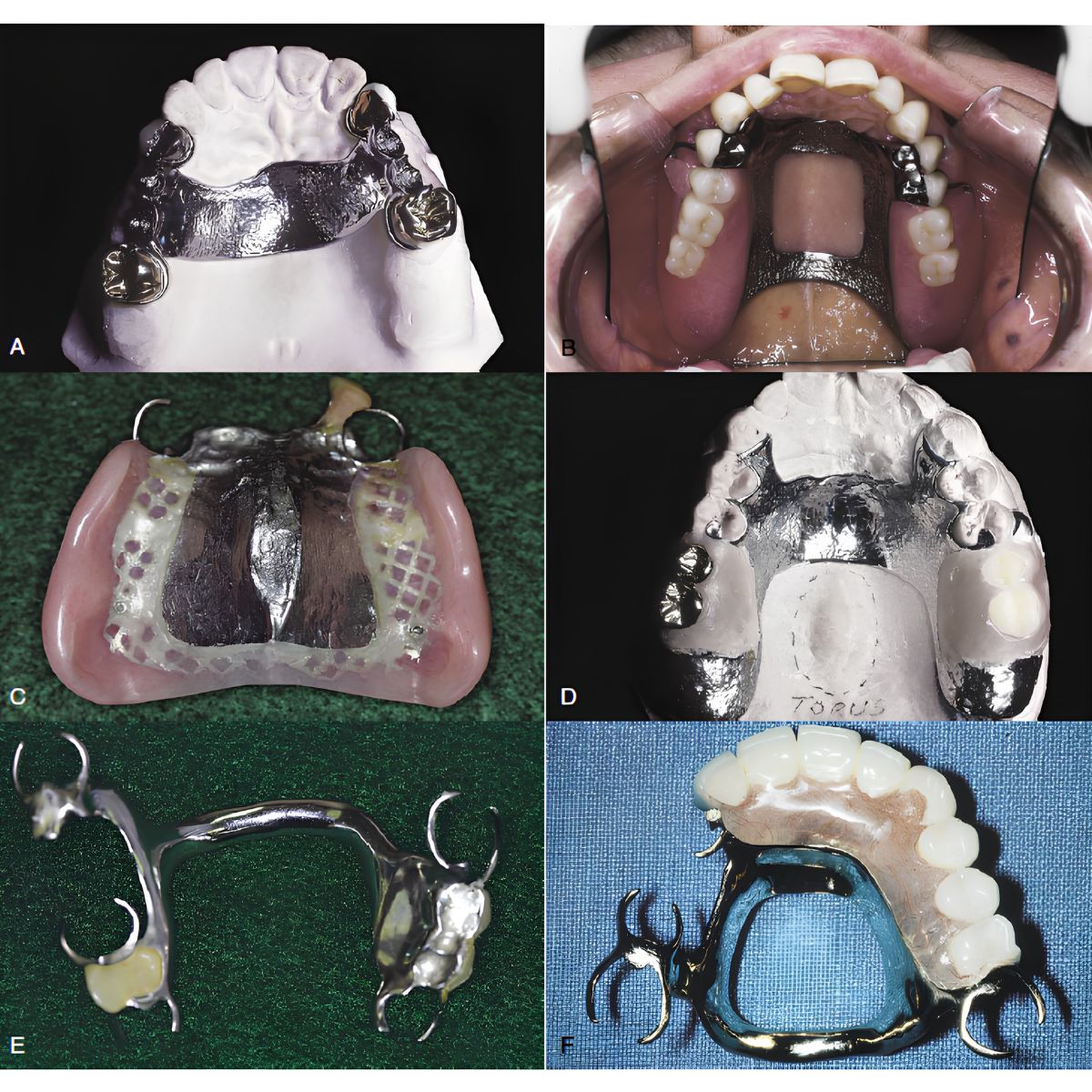
1. Single Palatal Strap (A)
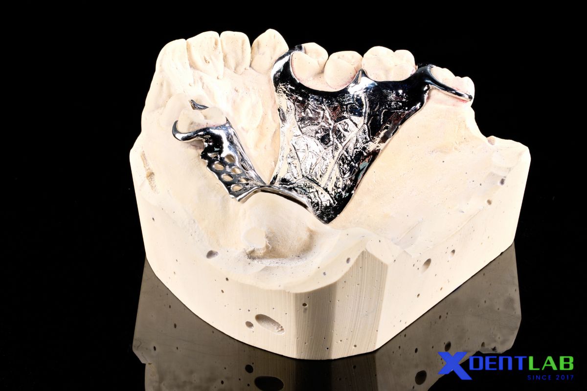
A single palatal strap is a single band of metal, generally 8mm or wider, running mediolaterally across the palate. It is indicated when tooth support is adequate on both sides of the arch and full-coverage rigidity is not required. Width is the controlling variable: too narrow and the strap flexes under load; positioned too close to the gingival margin and it causes tissue irritation.
2. Combination Anterior and Posterior Palatal Strap-Type Connector (B)
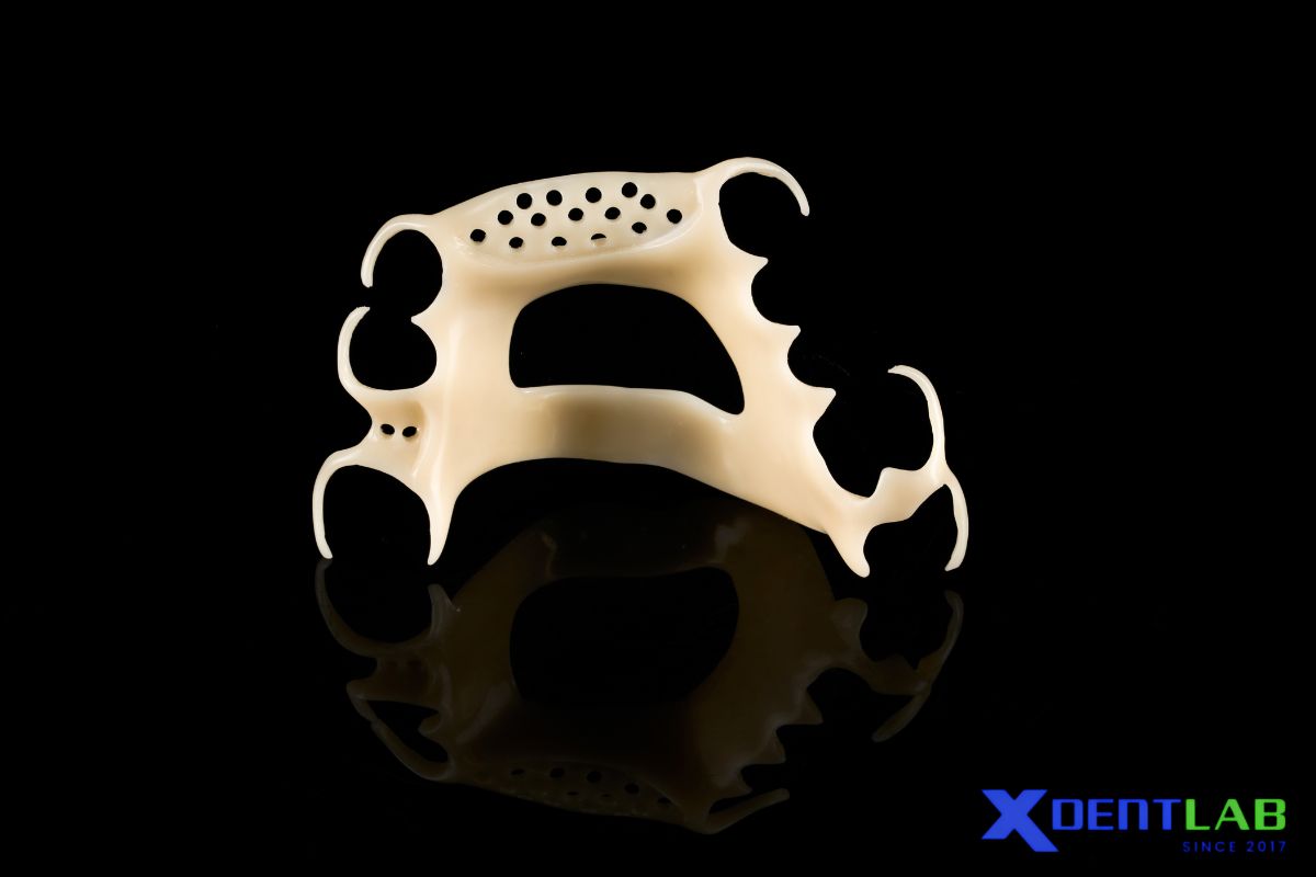
Two straps, one anterior and one posterior, either joined by a connecting bar or kept as separate units depending on the design. This configuration retains the rigidity of a strap connector while distributing support over a wider palatal area. It is typically indicated for longer edentulous spans or cases requiring indirect retention at more than one location.
3. Palatal Plate-Type Connector (C)
A palatal plate-type connector is a full or near-full palatal coverage. Indicated for extensive edentulous areas, limited residual ridge support, or cases requiring maximum stress distribution and indirect retention. It is the most rigid of the six designs by virtue of surface area, and also the one most likely to be noticed by the patient in terms of bulk and reduced tongue space. It should be selected because the case requires that level of support, not by default.
4. U-Shaped Palatal Connector (D)
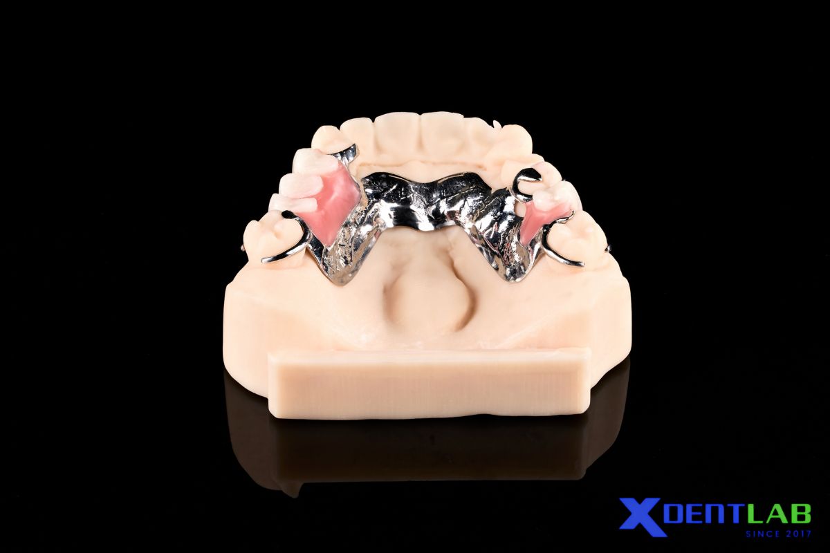
A U-shaped palatal connector is a horseshoe-shaped connector following the lingual and palatal surfaces of the remaining teeth without crossing the midline of the palate. Its primary indication is the presence of a torus palatinus or other unyielding midline structure that cannot be reasonably relieved. Because it lacks a direct anterior-posterior connection across the palate, it is inherently less rigid than the strap or plate designs and often requires increased bulk to compensate.
A narrow, rounded or half-oval bar, placed further posteriorly than a strap. It is the least rigid of the six connector types and the most conservative in terms of tissue coverage. Its use should be limited to short edentulous spans with strong natural tooth support, since it does not provide sufficient cross-sectional strength for more demanding cases.
Two narrower bars, one anterior and one posterior, connected laterally rather than joined into a broad strap or full plate. This design increases rigidity over a single bar through triangulation across the palate, while keeping coverage more conservative than a strap or plate connector. It functions as a middle-ground option for cases that exceed the capacity of a single bar but do not require full coverage.
How Maxillary Major Connectors Are Designed
Blatterfein's 1953 method remains the standard framework for maxillary major connector design, largely because it enforces a fixed sequence of evaluation rather than leaving connector selection to preference. The method proceeds in five steps, worked directly from the diagnostic cast.
Step 1: Outline the primary bearing areas
These are the regions the denture base will cover.
Step 2: Outline the nonbearing areas
This includes the tissue within 5–6mm of the remaining natural teeth, unyielding structures along the median palatal raphe (including any torus), and palatal tissue posterior to the vibrating line.
Step 3: Determine the connector area
Once bearing and nonbearing areas are mapped, the remaining palatal territory defines where connector components can be placed. Connector type should not be selected before this step is complete; doing so risks designing a connector for space that doesn't actually exist.
Step 4: Select the connector type
Selection is based on four factors: mouth comfort, rigidity, the location of the denture bases, and the need for indirect retention. A double-strap design typically offers the best rigidity-to-bulk ratio and is favored where anatomy allows. Edentulous span location constrains the choice further. Anterior edentulous areas rule out a posterior-only strap; posterior edentulous areas rule out an anterior-only strap, since the connector must extend to where functional stress is concentrated. Any requirement for indirect retention must be built into the connector outline at this stage.
Step 5: Unify the design
The denture base areas and the selected connector components are joined into a single rigid outline. This is also where the decision on full palatal coverage, if indicated, is finalized.
The value of this sequence is procedural discipline. Bearing areas first, exclusion zones second, available space third, connector selection fourth. Reversing that order, choosing a connector type before mapping the palate, is a common source of design errors that surface only after the framework is cast.
Selecting the Right Connector for the Case
None of the six connector types is a default choice. Selection should follow tooth support, not habit.
- Strong bilateral tooth support with short spans: single palatal bar or single strap
- Longer spans or multiple indirect retention sites: combination anterior-posterior strap
- Midline torus or unrelievable anatomy: U-shaped connector
- Extensive tissue-supported areas or compromised periodontal support: palatal plate
- Moderate support requirements between a bar and full coverage: anterior-posterior bars
As a general rule, rigidity requirements increase as tooth support decreases. Cases with strong abutments and limited edentulous spans tolerate narrower, more conservative connectors. Cases with longer spans, distal extensions, or reduced periodontal support require broader coverage to prevent flex and protect the remaining dentition.
This decision, made correctly at the design stage, is what determines whether a framework performs as intended once it's seated. It follows the same underlying logic used in mandibular major connector selection, applied to a different set of anatomical constraints.
References
McCracken's Removable Partial Prosthodontics.
About XDENT LAB:
We are experts in Lab-to-Lab Full Service from Vietnam, with the signature services of Removable, meet U.S. market standards, FDA-registered, ISO 13485-certified. Founded in 2017, from local root to global reach, we scale with 2 Factories with over 100+ employees.
Our Commitments Built on “Trusted. Commitment. Quality”
- Commit to Large-Scale Manufacturing, high volume, remake rate < 1%.
- Commit to 5-Year Warranty
- Commit to Competitive Price
XDENT LAB | A Trusted Lab-to-Lab Service from Vietnam
Share this post:
Related Posts
See a real case produced by XDENT LAB, a dental lab outsourcing in Vietnam that serves US customers with high quality and optimized cost.
See 5 completed Acrylic RPD cases from XDENT LAB, a Vietnam dental laboratory serving US, Europe, and Australia. Reliable lab to lab subcontract partner since 2017.

Learn how fixed prosthodontics supports dental lab outsourcing with scalable production, precise workflows, material consistency, and reliable restorative quality.

